OpenEEPROM, the Universal Programmer
Earlier this year I started building a 6502-based computer on breadboards. My goal was ultimately to map the system onto a PCB and create a single-board computer. But it’s August now and I’ve made very little progress on the project. The main reason boils down to one thing: I’m cheap.
You see, I’d gotten to the point where the CPU was wired up to a ROM chip. At this point, I needed to start programming the ROM so that I could experiment with the CPU, connect and test out RAM, etc. But I didn’t have a programmer. The obvious choice was a MiniPRO T86xx programmer like Ben Eater uses in his videos for the same purpose. But that thing costs $80… Frankly, I’m sure I’d get my money’s worth, but I just couldn’t bring myself to spend that much on it. To be fair, I could probably find a cheaper one that works well enough for as low as $30. But even that was more than I felt like spending, plus I’d have to wait a few days for shipping. Why do that when instead I could spend the next few months building my own? Enter ~OpenEEPROM~ gasps.
OpenEEPROM
OpenEEPROM is the many-months-long culmination of multiple attempts at creating a universal programmer. It’s free and open source. The term OpenEEPROM is overloaded. Not only is it the name of the project, but it’s also the name of the protocol around which the project is built. The OpenEEPROM protocol is a set of commands for programming parallel and SPI chips (and I2C eventually). To be used, the protocol requires two components:
- A programmer running firmware that implements all of the commands.
- A host that sends and receives commands to and from the programmer.
The programmer is responsible for handling the digital signals to and from a memory chip, while the host serves as the user interface running on PC. A common transport layer must be implemented by both the host and the programmer to enable communication between them, but there’s no restriction on what kind of transport layer is used except for which peripherals are available on the programmer. For example, if the programmer has a USB peripheral, the host can send commands over USB. If the programmer has a UART, the host can send commands over a serial port. If the programmer has a protocol stack, the host can send commands over TCP.
The Protocol
The protocol is little-endian byte-stream-oriented and lays out the exact format of every command, its parameters, and its return value(s). Every command will return at least a response status byte:
- ACK: 0x05, indicating the command was run successfully
- NAK: 0x06, indicating the command failed
The command set includes commands such as set_address_hold_time, parallel_read, set_spi_clock_freq,
and spi_transmit. The set is designed to be as small as possible while enabling enough control for
any kind of EEPROM or flash chip to to be programmed using drivers written on the host side.
The Programmer (Firmware)
The OpenEEPROM project contains a firmware implementation.
To maximize its usefulness, I’ve tried to make it simple to port the firmware to new MCUs.
Porting to a new MCU requires that you implement a programmer interface and a transport interface.
The programmer interface covers all of the digital IO functionality like setting
the value on a parallel address bus or transmitting bytes over SPI. The transport interface covers the communication
functionality needed to send and receive data to and from the host. These interfaces are best implemented using
a BSP for the MCU.
The Host
The OpenEEPROM project also contains a
Python host implementation.
At the lowest level is the BaseTransport interface.
BaseTransport hides the details of a transport layer behind two methods, send and receive. They work by sending
or receiving n bytes, an abstraction that plays well with the stream-oriented nature of the OpenEEPROM protocol.
Currently there are two classes that implement the interface: SerialTransport and TcpTransport.
Above the transport layer is the OpenEEPROMClient class. OpenEEPROMClient is initialized with a BaseTransport
object and uses it to implement all of the OpenEEPROM protocol commands. This allows you to make calls like
OpenEEPROMClient.parallel_read to the programmer without worrying about which actual transport
medium is used.
Chip drivers implement the BaseChip interface, which includes read, write, and erase methods and a
client: OpenEEPROMClient attribute. client is used to implement the RWE methods.
Additional chip-specific methods can be adde to the class.
For example, some chips support software-enabled protection or have status registers that can be queried.
A Robust Command Set
When it came to the protocol command set, I racked my brain for quite a while trying to decide on the minimum functionality necessary to enable programming any kind of parallel or SPI chip from the host side. The commands would need to be able to account for any differences that could possibly exist across chips.
For SPI, this is pretty straight forward. Every chip has essentially the same physical interface. It boils down to three main considerations:
- SPI clock frequency.
- SPI mode.
- Chip-specific commands (e.g, the first byte you transmit is a command byte).
Point 1 is straight forward. Have a command for setting the frequency. Done.
For Point 2, SPI devices may use one of four different modes:
- Mode 0 - clock low in idle state, data sampled on rising edge and shifted out on falling edge.
- Mode 1 - clock low in idle state, data sampled on falling edge and shifted out on rising edge.
- Mode 2 - clock high in idle state, data sampled on rising edge and shifted out on falling edge.
- Mode 3 - clock high in idle state, data sampled on falling edge and shifted out on rising edge.
And pratically all devices support Mode 0 anyway. Like Point 1, have a command to set the mode. Done.
And Point 3 really isn’t an issue because as long as there’s a command for transmitting data over SPI, the host side driver can handle any chip-specific commands.
Parallel chips are what I spent a long time trying to cover. The way I saw it, there are so many permutations of programming sequences for a parallel chip. So many pins, so many different timings. I was staring at diagrams like this:
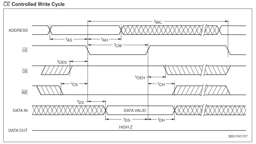
and I was terrified by them (this is for an AT28C256, btw).
But I finally came to the realization that was right in front of me the whole time.
Parallel chips all behave in essentially the same way. For a read:
- Enable the chip and allow it to drive the data bus (pull down the CE line and the OE line).
- Set the address bus with the desired address.
- After a chip-specific duration (address hold time) read the data on the data bus.
- Disable the chip.
This can be repeated however many times is desired.
A write is just slightly more involved:
- Set the address bus(before enabling the chip, otherwise we risk corrupting the data at some other address).
- Set the data bus.
- Wait the address hold time.
- Enable the chip and and enable writing (pull down the CE line and the WE line).
- Wait a chip-specific duration (CE pulse-width time)
- Disable the chip.
Depending on the chip, these steps may be repeated a certain number of times before a write cycle has to be performed, which will require a wait on the order of milliseconds.
Aside from that, these two processes essentially characterize the read and write cycles for any parallel chip. So the only parameters that need to be controllable are the address hold time and CE pulse-width time.
Note: I’m assuming that the control lines on a parallel chip (CE, OE, WE) are always active low. I’m not certain this is true 100% of time time, and if it’s not that’s one extra parameter to consider. However, as far as I know, this does hold true, as the pinout that indicates these lines are active low is a JEDEC standard for parallel chips.
Usage
Assuming you have a programmer that speaks OpenEEPROM over a serial port, you can use the OpenEEPROM CLI tool built on top of the Python host. For example,
write the contents of input.txt to a 25LC320 SPI EEPROM:
$ python -m openeeprom write --file input.txt --chip 25LC320 --serial /dev/ttyACM0:115200
or to read the contents of an Atmel 28C256 parallel EEPROM into output.bin:
$ python -m openeeprom read --file output.bin --chip AT28C256 --serial /dev/ttyACM0:115200
You can also import OpenEEPROM directly:
from openeeprom.transport import SerialTransport
from openeeprom.client import OpenEEPROMClient
from openeeprom.chip import AT28C256

client = OpenEEPROMClient(SerialTransport(port='/dev/ttyACM0', baud_rate=115200))
chip = AT28C256()
chip.connect(client)

contents = chip.read(0, chip.size)
Future Additions
There are lots of improvements/features to be made. The few that stick out to me the most are:
-
Add I2C support to the OpenEEPROM command set.
-
Add a GUI memory viewer to the Python host package. The GUI would allow you to view the contents of a chip, modify individual bytes, and select a file from a file explorer to flash to the chip.
-
Create an STM32 port for the OpenEEPROM firmware.
-
Create a custom board with an attached MCU, 40-pin DIP socket, and USB-A header that I can use as a handy programmer.
There’s certainly enough here to keep me busy, but I think it’s about time I get back to my 6502 SBC project.
View the OpenEEPROM source here.